Eighteen measurements, organised around the field and the station itself.
The Generation 4 concept combines field measurements, crop observation, device health and safety in one modular station. It remains subject to professional engineer sign-off.
One station. Four physical sensing domains.
- 01 Soil at root depth
One 7-in-1 probe reads the root zone.
- 02 Water + weather
Six readings describe conditions beside the crop.
- 03 Crop + pest observation
Cameras and pest hardware monitor activity above the soil.
- 04 Health + safety
Power, enclosure and structure show station condition.
One probe. Seven soil readings.
Installed permanently at root depth.
- 01 Root depth One fixed location for all seven readings.
- 02 Wired connection All seven readings travel through one wired RS485 connection.
| Measurement | Range | Accuracy / unit |
|---|---|---|
| Soil moisture | 0–100 %RH | ±3% |
| Soil temperature | −40 to 80 °C | ±0.5 °C |
| Electrical conductivity | 0–20,000 µS/cm | Range specified |
| pH | 3–9 | ±0.3 |
| Nitrogen | 0–1,999 mg/kg | ppm / mg/kg |
| Phosphorus | 0–1,999 mg/kg | ppm / mg/kg |
| Potassium | 0–1,999 mg/kg | ppm / mg/kg |
Swipe the table to see the specified detail
Local conditions are measured beside the crop.
- Field water level Range 0–500 mm · ±0.5 cm
- Air temperature Range −40 to 125 °C
- Air humidity Range 0–100 %RH
- Illuminance Range 1–65,535 lux
- Rainfall Resolution 0.2 mm per tip
- Wind speed Range 0–30 m/s
Cameras and pest hardware monitor crop activity.
- 01 Two cameras 2 MP · infrared · IP67
Scheduled views of the crop canopy from two positions.
- 02 Infrared insect counter Counts per hour
Records insect activity between image captures.
- 03 Ultrasonic repeller Integrated at the station
Provides an active deterrent beside the monitoring hardware.
How the 18-measurement total is counted.
- 08 Agronomic
Seven soil readings plus field water level describe the crop's immediate growing environment.
- 08 Power + health
Battery, circuit, enclosure and structural telemetry describe whether the station itself is healthy.
- 02 Safety
A critical-water float and service-door switch remain independent of the primary sensing chain.
Additional instruments Weather and crop/pest instruments are additional and are not included in the total of 18.
The station measures itself as well as the field.
Operators need to know whether a questionable reading came from the crop or from the instrument. Health telemetry provides that second layer of evidence.
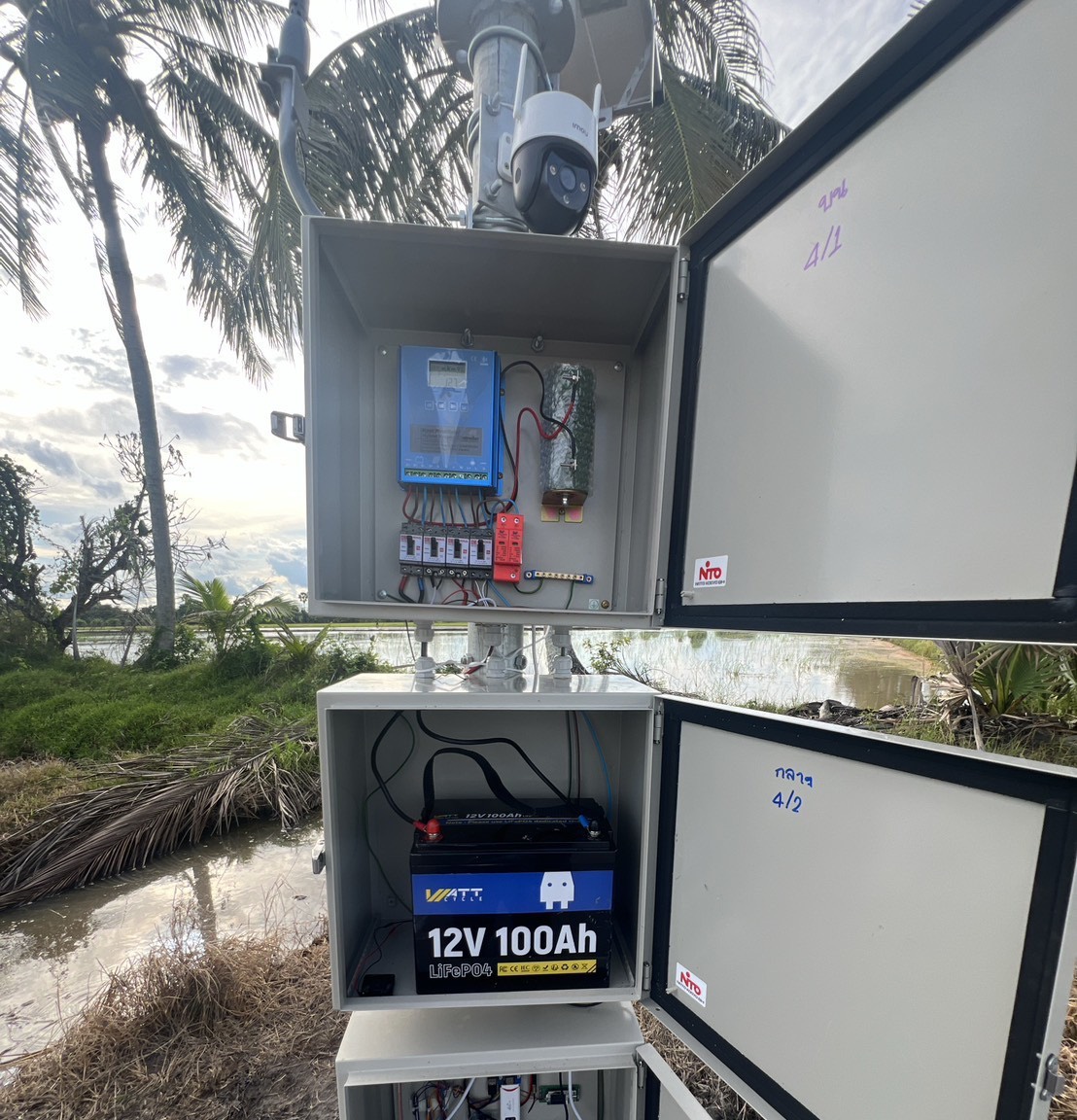
- 01 Power state Battery voltage · Battery current · State of charge
Shows available energy and whether the battery is charging or discharging.
- 02 Battery temperature Battery-cell temperature
Places battery behaviour beside its thermal condition.
- 03 Circuit loading Current on three independent circuits
Separates major loads so abnormal demand is easier to locate.
- 04 Service bay Temperature + humidity
Records the environment around compute and power electronics.
- 05 Structure Three-axis tilt + vibration
Provides evidence of movement or an abnormal physical condition.
The measurement chain is protected for field use.
- Critical-water float Rising-water warning
- Service-door switch Maintenance access record
- IP68 probe Sealed probe body
- Vacuum potting Stops water ingress
- Shielded pair Reduces interference
- RS485 link 5–24 VDC · station link
Replace one probe—not the whole station.
- 01 Verify Confirm the reading
- 02 Isolate Locate the component
- 03 Replace Service one module
Hardware creates the reading. Software decides what happens next.
Follow a measurement into validation, timestamping, local storage and priority handling at the pole.